Butterfly valves are widely used in industries such as water treatment, oil and gas, HVAC, and chemical processing due to their compact design and efficient flow and cost-effective control.
However, one of the most common problems with butterfly valves is leakage. Leaks can occur internally (through the valve seat) or externally (around the valve stem or valve body). Leaks can be minor or major, resulting in reduced system efficiency, or serious safety risks, environmental issues, or costly downtime.
Therefore, understanding the root causes of these leaks and implementing effective solutions is critical to ensure reliable valve performance.
---
Types of Butterfly Valve Leaks
Before diving into the causes and solutions, let’s first classify the common leaks in butterfly valves:
a. Internal Leakage: Fluid passes through the valve when it is in the closed position, indicating that the valve seat or disc cannot form a tight seal.
b. External Leakage: Fluid escapes from the valve body, usually around the valve stem, packing, or flange connection, compromising the seal.
Both types of leaks can stem from design, installation, operation, or maintenance-related factors.
Below, we will explore the main causes and corresponding solutions for each type of leak.
---
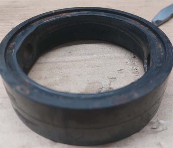
1. Worn or damaged seals
A common cause of internal leakage is the degradation of valve sealing components (such as elastic liners or metal seats).
1.1 Causes
- Material degradation: Prolonged exposure to corrosive liquids, high temperatures or ultraviolet radiation can cause seals to harden, crack or lose elasticity.
- Abrasive media: Fluids containing sand, gravel or other particles will corrode seals over time.
- Aging: Even under less demanding conditions, seals will naturally deteriorate over time, reducing their ability to fit the valve disc. This is inevitable natural aging.
- Excessive torque: The torque of the selected electric, pneumatic and other actuators is too large, and the valve disc applies too much pressure on the valve seat when closing, causing the valve seat to deform or even tear. Even when operated manually, applying excessive torque to large-diameter butterfly valves may cause deformation or damage to the valve seat.
1.2 Solutions
- Material selection: Select sealing materials that are compatible with the fluid and operating conditions. For example, use PTFE for chemical resistance, EPDM for water applications, and Viton for oil-based fluids.
- Regular maintenance: Implement a preventive maintenance program to inspect and replace seals before they fail. This is especially important in harsh environments.
- Protective coating: In abrasive applications, consider using valves with coated or hardened seats to extend the life of the seals.
- Optimize the actuator: According to the butterfly valve torque data given by the manufacturer, select an actuator with appropriate torque, or select an actuator with torque protection. In addition, when operating manually, excessive force should be avoided. Zfa recommends that if you are not sure, you can use a handle or worm gear actuator with torque limitation.
- ---
2. Improper installation
Leakage is often caused by errors during valve installation, affecting internal and external seals.
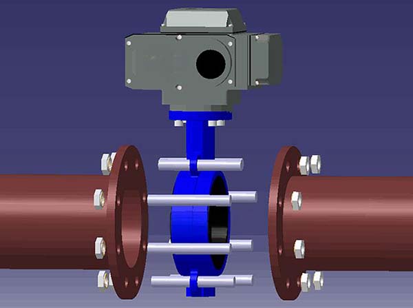
2.1 Causes
- Misalignment: If the valve is not properly aligned with the pipe, the disc may not seat properly, resulting in internal leakage.
- Insufficient torque: Insufficient tightening of the flange bolts can cause external leakage at the valve pipe interface.
- Over-tightening: Excessive torque can cause deformation of the valve body or seat, which can prevent the disc from fully closing and cause internal leakage.
2.2 Solution
- Alignment check: During installation, use an alignment tool to ensure that the valve is centered in the pipe. It is also necessary to verify that the disc moves freely without contacting the pipe wall.
- Torque specification: Follow the manufacturer's recommended torque value for flange bolts and use a calibrated torque wrench to achieve uniform compression of the gasket.
- Gasket selection: Use high-quality, high-elastic gaskets that are compatible with the valve and pipe materials. Also make sure the gasket size is appropriate to avoid excessive compression or gaps.
- ---
3. Disc interference
Internal leakage may occur when the disc cannot fully close due to physical interference with the surrounding pipe or flange.
3.1 Cause
- Pipe diameter mismatch: If the pipe ID is too small, the disc may hit the pipe wall when closing.
- Flange design: Raised-face flanges or improperly sized mating surfaces can hinder the disc from moving.
- Debris accumulation: Solids or scale that accumulate inside the valve can prevent the disc from seating properly.
3.2 Solution
- Compatibility verification: Before installation, confirm that the valve disc diameter is compatible with the pipe ID.
- Flange adjustment: Follow standards such as ANSI or DIN to use flat flanges or gaskets to ensure disc clearance.
- Cleaning work: Flush the system before valve operation to remove debris, and install upstream filters if conditions permit to prevent future accumulation.
4. Failed stem packing
External leakage usually occurs around the valve stem, which is due to problems with the packing or seals that prevent fluid from flowing out along the axis.
4.1 Cause
- Wear: Over time, packing materials such as PTFE or graphite will wear due to stem movement or pressure.
- Temperature fluctuations: Based on the principle of thermal expansion and contraction, repeated temperature fluctuations can cause the packing to shrink, loosen, and even rupture.
- Improper adjustment: If the packing gland is too loose, the fluid may leak; if it is too tight, it may damage the valve stem or restrict movement.
4.2 Solution
- Packing maintenance: Regularly check and replace worn packing materials.
- Temperature considerations: Select packing materials suitable for the system temperature range, such as flexible graphite materials for high-heat applications.
- Gland adjustment: Tighten the packing gland to the torque specified by the manufacturer, check for leaks after adjustment and avoid over-compression.
---
5. Excessive pressure or temperature
When operating conditions exceed the design limit of the valve, leakage may occur, affecting internal and external seals.
5.1 Causes
- Excessive pressure: Pressure exceeding the valve rating can deform the valve seat or disc, making it impossible to seal.
- Thermal expansion: High temperatures can cause components to expand unevenly, causing seal aging, softening or even carbonization, which can affect the fit of the sealing surface, loosen the seal or cause external leakage at the joint.
- Cold brittleness: Under conditions below -10 degrees, the seal may become brittle and crack, causing leakage.
5.2 Solutions
- Appropriate pressure and temperature ratings: Select valves with pressure and temperature ratings that exceed the maximum system conditions and consider safety margins.
- Pressure relief: Install an upstream pressure relief valve or regulator to prevent over-pressure.
- Insulation/heating: Use insulation sleeves or heat traces in cold climates to prevent freezing.
5.3 Material temperature comparison table
Below are the media and temperature ranges corresponding to seals of various materials.
| NAME | APPLICATIONS | TEMP. RATING |
|---|---|---|
| EPDM | Water, potable water, seawater, alcohols, organic salts dissolutions, mineral acid solutions, mineral bases alkaline | -10℃ to 110℃ |
| NBR | Mineral and vegetable oils, gas, non-aromatic hydrocarbons, animal fats, vegetable fats, air | -10℃ to 80℃ |
| VITON | Acids, fats, hydrocarbons, vegetable and mineral oils,fuels | -15℃ to 180℃ |
| Nature Rubber | Salts, hydrochloric acid, metal coating solutions, wet chlorine. | -10℃ to 70℃ |
| Silicon Rubber | Low and high-temperature resistance, food grade Hydrocarbons, acids, bases, atmosfpheric agents | -10℃ to 160℃ |
| PU | nonaggressive chemical applications such as water, wastewater and seawater | -29℃ to 80℃ |
| HNBR | Water, Potable Water, Wastewater. | -53℃ to 130℃ |
| Hypalon | Mineral acid dissolutions, organic and inorganic acids, oxidizing substances, | -10℃ to 80℃ |
| PTFE | water, oil, steam, air, slurries, and corrosive fluids | -30℃ to 130℃ |
| SS+Graphite | High temperature and high pressure environments, such as steam systems, chemical and petroleum industries. | -200°C to 550℃ |
| SS+Stelite | all medium | -200°C to 600°C |
---
6. Cavitation and corrosion
6.1 What is cavitation
Cavitation is caused by the sudden drop in pressure of the liquid medium to the vapor pressure of the liquid at the throttling part of the valve (such as between the butterfly plate and the valve seat), resulting in local gasification of the liquid to form bubbles. When these bubbles move to the high-pressure area with the fluid, they collapse rapidly, generating shock waves and microjets, which in turn cause erosion and damage to the valve sealing surface, valve seat and valve body.
Although cavitation and corrosion are primarily a performance issue, it can indirectly cause leakage by damaging the sealing surface.
6.2 What is corrosion?
Corrosion is caused by chemical or electrochemical reactions on the material surface of the butterfly valve due to long-term contact with corrosive media (such as acid, alkali, salt solution or high-temperature steam), resulting in damage to the valve sealing surface, valve stem, valve seat or valve body.
6.3 Causes
- High pressure drop: Rapid pressure changes will produce bursting bubbles, which will corrode the valve disc or valve seat.
- Corrosive flow: The medium contains acids, alkalis, salts, etc., which react directly with the metal surface, causing the sealing surface and valve body to be gradually dissolved or corroded and thinned.
- Abrasive media: High-speed fluids containing particles will wear the sealing edge over time.
6.4 Solutions
- Flow control: Correctly determine the valve size to minimize pressure drop and use flow coefficient (Cv) calculations to meet system requirements.
- Material upgrade: Choose corrosion-resistant materials such as stainless steel or hard surface coatings for valve discs and valve seats.
- System design: Reduce flow rate by increasing the pipe diameter or adding a pressure reducing device upstream.
6.5 CV Value Table
| Cv Value- Flow Rate Coefficient DN50 to DN1400 | |||||||||
|---|---|---|---|---|---|---|---|---|---|
| Size(mm) | 10° | 20° | 30° | 40° | 50° | 60° | 70° | 80° | 90° |
| 50 | 0.1 | 5 | 12 | 24 | 45 | 64 | 90 | 125 | 135 |
| 65 | 0.2 | 8 | 20 | 37 | 65 | 98 | 144 | 204 | 220 |
| 80 | 0.3 | 12 | 22 | 39 | 70 | 116 | 183 | 275 | 302 |
| 100 | 0.5 | 17 | 36 | 78 | 139 | 230 | 364 | 546 | 600 |
| 125 | 0.8 | 29 | 61 | 133 | 237 | 392 | 620 | 930 | 1022 |
| 150 | 2 | 45 | 95 | 205 | 366 | 605 | 958 | 1437 | 1579 |
| 200 | 3 | 89 | 188 | 408 | 727 | 1202 | 1903 | 2854 | 3136 |
| 250 | 4 | 151 | 320 | 694 | 1237 | 2047 | 3240 | 4859 | 5340 |
| 300 | 5 | 234 | 495 | 1072 | 1911 | 3162 | 5005 | 7507 | 8250 |
| 350 | 6 | 338 | 715 | 1549 | 2761 | 4568 | 7230 | 10844 | 11917 |
| 400 | 8 | 464 | 983 | 2130 | 3797 | 6282 | 9942 | 14913 | 16388 |
| 450 | 11 | 615 | 1302 | 2822 | 5028 | 8320 | 13168 | 19752 | 21705 |
| 500 | 14 | 791 | 1674 | 3628 | 6465 | 10698 | 16931 | 25396 | 27908 |
| 600 | 22 | 1222 | 2587 | 5605 | 9989 | 16528 | 26157 | 39236 | 43116 |
| 700 | 36 | 1813 | 3639 | 6636 | 10000 | 14949 | 22769 | 34898 | 49500 |
| 800 | 45 | 2387 | 4791 | 8736 | 13788 | 20613 | 31395 | 48117 | 68250 |
| 900 | 60 | 3021 | 6063 | 11055 | 17449 | 26086 | 39731 | 60895 | 86375 |
| 1000 | 84 | 4183 | 8395 | 15307 | 24159 | 36166 | 55084 | 84425 | 119750 |
| 1200 | 106 | 5370 | 10741 | 19641 | 30690 | 46065 | 70587 | 107568 | 153450 |
| 1400 | 174 | 8585 | 17171 | 31398 | 49060 | 73590 | 112838 | 171710 | 245300 |
---
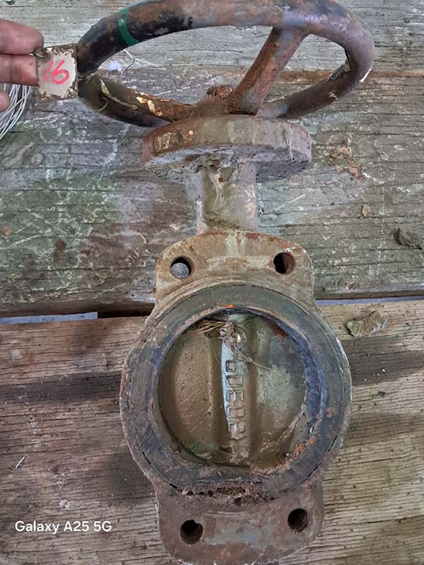
7. Manufacturing Defects
Sometimes, leaks originate from defects in valve construction that can be detected during initial use or testing.
7.1 Causes
- Casting defects: Porosity or cracks in the valve body can cause external leakage.
- Sealing surface problems: Uneven machining of the disc or seat can prevent proper sealing, resulting in internal leakage.
- Assembly errors: Improper installation of seals or misalignment of components during manufacturing can cause leaks.
7.2 Solutions
- Quality assurance: Buy from reputable manufacturers with certifications such as ISO 9001, and request a pressure test report (e.g., according to API 598) to verify leak-proofness.
- Pre-installation testing: Perform hydrostatic or pneumatic leak tests before installation to identify defects, and return faulty units to the supplier.
- Warranty claims: Make sure the valve comes with a warranty that covers manufacturing defects so that it can be replaced if leaks are discovered early.
---
8. Conclusion
Butterfly valve leakage, solving these problems requires a combination of selecting the right valve, careful installation, regular maintenance, and system optimization. By selecting materials suitable for the application, following installation guidelines and monitoring operating conditions, users can significantly reduce the risk of leakage.
Butterfly valve leakage problems may be caused by a variety of factors, and different solutions are required for different leakage types. Whether it is internal leakage or external leakage, it can usually be attributed to worn seals, installation errors, valve disc interference, valve stem packing problems, excessive pressure/temperature, manufacturing defects or corrosion. The leakage risk of butterfly valves can be effectively reduced through reasonable selection, correct installation, regular maintenance and optimized operation. For critical applications, consulting valve manufacturers or system engineers can further ensure leak-free operation and improve system safety and operating efficiency.